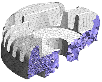
The mesh consists of an overlapping grid over a background domain for a FINE™/Marine simulation. Some applications are very well suited for that concept: as proof, we used it for a hydrofoil simulation (all details here). As such, IGG™ or AutoGrid™ are two very good candidates to provide such an initial grid! But the refinements can actually be started from any type of cell alignment: straight or curved following any kind of shape, and it can support different cell distribution. Indeed, for a volume-to-surface approach, an unstructured mesh is classically based on an initial Cartesian or cylindrical grid that is further refined. NUMECA also proposes the idea of using an initial structured grid for an unstructured mesh generation.

As a result, the majority of the mesh is done with a structured grid, but the most complex part is done with an unstructured approach.Īnd that’s not all. Hence, a technique consists of removing a few blocks from a structured mesh, (away from the difficult part), and then reinserting an unstructured mesh block instead, which includes the complex tip geometry (as shown in the example below). But some parts of the geometry could still be tricky for any structured mesh generator. Pushing the idea a bit further: since NUMECA offers both meshing methodologies in OMNIS™, what about using them at different locations within a single geometry? We previously stated that blades are best created with a structured meshing tool like AutoGrid5™ (which can also do a lot of particular configurations such as cooling holes, asymmetric end walls, casing treatment, etc.). We can definitely identify a few others, like an impeller and its volute, a ship, and its propeller, etc. Hence, we are seeing more and more users applying the best methodology depending on the geometry component. As such, 19 minutes are necessary if we can afford to run them at the same time. Each piece can be done separately, and the mesh generation itself in parallel. As an example, a complete turbomachine is shown below (the complete simulation is detailed here). NUMECA has a reputation for providing the right technology for the corresponding application, and as such, our engineers have developed a solution within our OMNIS™ environment where users can switch between meshing approaches in a single click, enabling them to not only access within the same project-but also within the same view-all the pieces of the geometry, whatever the preferred meshing technique.įor blade-like geometries, users can apply a structured approach in OMNIS™, and for non-rotating parts, like combustion chambers, volutes, etc, users can apply an unstructured approach. This seemingly no-win situation is where NUMECA offers an innovative solution, however. However, there is a third factor: flow solvers must be able to read the type of meshes behind them, and as most flow solvers only accept either structured or unstructured meshes, this is a no-win situation. This question could be answered easily if the only factors to consider were the physics to be captured and the type of accuracy needed. In other words, as soon as a geometry falls outside of the classic range of structured mesh applications, the debate starts: when should we adhere to creating structured meshes versus simply switching to unstructured meshes?

CFD users have to spend a lot of time defining these new topologies and cleaning the geometry before even starting to mesh. The problem with certain geometries is that they lack accuracy in terms of definition (“dirty” or “unclean”), and they do not present any particular trends to which standard structured mesh topologies can be applied. These types of meshes, which AutoGrid5™ excels at producing, are perfectly suited for turbomachinery applications with any kind of blade geometries.Īs the complexity of geometries began to increase (now often with more than 10k surfaces), the need for another type of mesh-one with unstructured properties-arose. Structured meshes offer several main advantages, such as precision, speed of generation, and uniform distribution of cells.

In the following code, the geometry is modeled using three rectangles: lc = 0.In CFD history, structured meshes came first, and they are still in use today. In such cases, you should partition the problem geometry into distinct rectangles (planes with four corner points) so the Trasnfinite option could be applied to them. In your file, the plane is constituted from six points and Gmsh can't mesh it structured. In Gmsh only planes that have four corner points could be meshed with structured meshes using Trasnfinite option.


 0 kommentar(er)
